%20small.png)
Setting Up Your Model For External PLA
- Leanne Weaver
- Mar 14
- 4 min read
Content Links
Set up your job model so that you can export your job data to be used in a third-party pole loading analysis software platform - SPIDACalc, O-Calc, and Pole Foreman (version 7 or older).
Starting Point
Creating A New Model
If you already have a model to use but needs to be setup for External PLA, skip to the next section.

Otherwise, navigate to the Model Editor and click the blue "+" button to create a new model.

After entering a name for your new model, choose "Guided Setup" when asked how you would like to create your model.

Next, answer "Yes" to "Will this model require Make Ready?"

Then choose which set of Make Ready rules you'll want to utilize - GO 95 or NESC.

Answer "Yes" to "Will this model require Pole Loading?" Once you have answered "Yes," go on to Next Steps.
Importing To An Existing Model
If you want to add pole loading analysis capabilities to an existing model to leverage External Pole Loading, make sure your model is set up for Make Ready. If it's not, click the "Import From Catalog" to import the Make Ready Engineering catalog (refer to screenshot below).

With the model set up for Make Ready, you can import the catalogs needed for PLA.

Click on "Import From Catalog" and find the PLA Exports catalog, as well as the catalog specific to your external PLA platform (i.e. Spida Calc client file, O-Calc catalog, and Pole Foreman database).

Then you'll want to click this "Import PLA" button next to the "Import From Catalog" button. Move on to the Next Steps section to continue the process.
Next Steps
Whether you created a model or started preparing an existing one, you will then find yourself on this screen (seen in the screenshot below) with four checkbox settings and a rounded square saying to "Drop File Here."

Include Integrated Pole Loading. (If you don't see this option but would like to use it, you may want to reach out to our sales team at sales@katapultengineering.com.) If you want to use this model for Integrated Pole Loading in addition to external pole loading, check "Include Integrated Pole Loading" and read the setup documentation corresponding with whichever third-party platform you will be using for external pole loading for details about how your client file is translated into Katapult Pro. We recommend keeping this option checked.
Skip Messengers (O-Calc and Spida Models). If you checked "Include Integrated Pole Loading," you will want to make sure that "Skip Messengers..." is also checked.
Pass Tensions Through to Export (O-Calc Models). We recommend keeping this checked at all times. If you have questions regarding this specific option, feel free to reach out to support@katapultengineering.com.
Clear Existing Pole Loading Specs. If you are creating a model, you may leave this unchecked. If you are editing an existing model, if this option is checked, it'll clear out any outdated Pole Loading Specs and import the updated Pole Loading Specs from the client file.
Upload your client file in the rounded square saying "Drop File Here." *If you're importing Pole Foreman database files, ensure to include both the progdata.mdb and framing.mdb files.

Once you upload your client file, you'll see this review page to review the data that will be added to the model. If you click the carrot arrow next to an item, it'll open a section with all the values that the software will carry over - these will be the different specifications, routines, input model groups, etc. Once you've determined that all the data you need is there and looks how you need it to, click "Continue" to create/update your model.
Configuration
There is a checklist of things to configure and review before utilizing pole loading in your job:
Configure Insert Com Spec tool
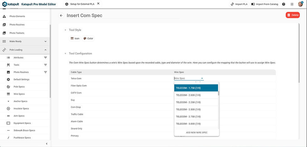
Open the "Tools" section of your model, open the Insert Com Spec tool that was imported with the PLA Import, and map the listed Wire Types to the corresponding Wire Spec provided in the dropdown; these values in the dropdown should be the specifications imported from your client file.
This mapping is one-to-one; map the Wire Spec to Wire Type regardless of diameter.
Without this mapping configured, the software will attempt to intelligently map the cable type and diameter to a given Wire Spec; the success of this attempt would depend on whether your Wire Specs are formatted in a way that the software is expecting.
Down guys are not included in this mapping table for the Insert Com Spec tool; if you need down guy specs other than the ones provided in our system, please reach out to support@katapultengineering.com.
Configure Insert Anchor Spec Tool

Again, open the "Tools" section of your model, open the Insert Anchor Spec that was imported with the PLA import, and map the listed Rod Size to the corresponding Anchor Spec provided in the dropdown; these values in the dropdown should be the specifications imported from your client file.
Review imported Photo Routines
Make sure that the Photo Routines you imported from your client file prompt for the correct specifications needed (i.e. Arm markers should prompt for Arm Spec, Insulator Spec for Insulators, Transformer Spec for Transformers, etc.)
Go to the "Photo Routines" section in the Model Editor, open the routine imported from your client file, and review its contents in the marker(s).
Set which markers will skip Hardware Angles when using Hardware Details tool
To set which equipment markers to skip for the Hardware Detail tool's "Enter Hardware Angles" step, you'll need to reach out to support@katapultengineering.com.
For example, if you have three separate markers for annotating the same piece of equipment, you can skip two of these markers so that the angle for that equipment is only entered once (reducing the risk for data inconsistency)
If you are importing your SPIDACalc Clientfile or Pole Foreman database, you'll want to reach out to support@katapultengineering.com for help with with configuring the following:
SPIDACalc:
Allow Missing Groundline Circumference
Default Slack Tension Adjustment
Default Wire Tension
Location Label
Order Endpoints By Next
Proposed Layer Name
Skip Span Point
Pole Foreman:
Verify default NESC Construction Grade
Verify default NESC Loading District
Verify default Anchor Settings
Anchor Type
Soil Class
Auto-boxing Cables
Export Open Secondary as Neutral Conductor Type
Export Bundled Primary as Neutral Conductor Type
Include only SCID in Label
Include SCID in Label
Max Ruling Span
No Adjacent Heights
Default Power Company
Ruling Span Local to Pole
תגובות